
Autonomous Robot Navigation [E160] – Final Project
The final project was a culmination of multiple labs, each requiring a two page report:
Final Project
Background
The Kalman Filter (KF) is a filtering and prediction technique for continuous systems; however, it is only limited to linear Gaussian systems. In order for the Kalman filter to be correct, its derivation relies on linear transformations. One method of applying this filter to nonlinear systems is to instead use a first-order Taylor series estimate. In a previous lab, we implemented a particle filter, which can be used to approximate most distributions with enough particles; however, particle filters are computationally expensive. The benefit of the Kalman filter is its closed form solution, making a very fast technique for Gaussian systems The unscented Kalman filter (also known as sigma-point belief propagation) is another method of linearizing nonlinear systems, for use in Kalman filtering. Instead of linearizing a system, like the EKF, the UKF propagates sigma points through the non-linear transformation. Sigma points are located at the mean and symmetrically along the main axes of the covariance.
Link to the final presentation: E160 UKF Final Presentation
Project Definition
Localize a differential drive robot in a known map, using an algorithm more accurate than an extended Kalman filter and more efficient than a particle filter.
Materials
The robot used in this report is a small, two-pound differential drive robot, shown in the figure below. The diameter of each wheel is 6.95 cm +/- 0.01 and the distance between the center of the two wheels is 14.15 cm +/- 0.01. Each wheel also has an encoder that is capable of measuring the relative rotation of each wheel with a resolution of 4.36*10^{-3} rad/tick.

Map
The particle filter was tested in simple hallway. The hallway has a footprint of approximately 4 meters by 4 meters, the specific measurements are shown in the figure below. To overcome the sensor’s limited range, the robot’s trajectory was place next to the walls.

UKF Algorithm
The following UKF pseudocode is from Chapter 4 of Sebastian Thrun’s text: Probabilistic Robotics.

Robot State
The UKF state consisted of three variables: the two dimensional position (x,y) and the robot’s heading (theta).


Experiment 1 – Convergence
This experiment looked at convergence rates for different types of initial disturbances.
Simulation
Theta-offset: Converged 4/5 times
XY-offset: Converged 5/5 times

Experiment 2 – Passive Tracking
Simulation
RMSE: 0.0331 m


Hardware
RMSE: 0.1841 m

Experiment 3 – Feedback Control
Simulation
RMSE: 0.0389 m


Hardware
RMSE: 0.1914 m


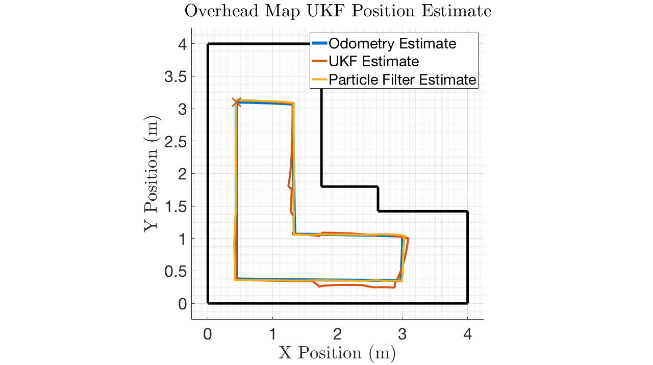
Experiment 4 – UKF and Particle Filter Comparison
Simulation
UKF RMSE: 0.0496 m
Particle Filter RMSE: 0.0183 m

